US Patent 7,791,353 B2
Introduction
Simple Circuit Concepts
Transmission lines
Faraday's law
Near and far fields
Spurious coupling mechanisms
- Direct conduction
- Capacitive coupling -problem
- Capacitive coupling -fixing
- Inductive coupling-problem
- Inductive coupling -fixing by twisted
- Inductive coupling -fixing by coax
- Electromagnetic pickup
- Examples
- Safety & star grounding
- Gnd loop resistance, inductance
- Low frequency behavior
- High frequency behavior
- Troubleshooting
- Methods for removing
Ground loop behavior at low frequency
To see how a low frequency ground loop behaves consider a system of six coaxial cables connected in a hexagon loop and let R1, …R6 represent the resistances of the outer conductors (shields) of these cables. This shield circuit is shown in Fig.12(A).
To see how a low frequency ground loop behaves consider a system of six coaxial cables connected in a hexagon loop and let R1, …R6 represent the resistances of the outer conductors (shields) of these cables. This shield circuit is shown in Fig.12(A).
Find ground loops fast!
-eliminate electical interference, fix star grounding
-eliminate electical interference, fix star grounding
US Patent 7,791,353 B2
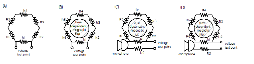
Figure 12. Shields of 6 coaxial cables connected in series to form a hexagonal loop. (A) no voltage across R1 in static situation, (B) voltage appears across R1 if loop links time-dependent magnetic flux, (C) field in cable shield adds to microphone voltage, (D) breaking of ground loop by disconnecting R6.
A voltmeter connected across R1 in Fig. 12(A) will indicate zero volts because there is no voltage source. However, if a time-dependent magnetic flux links the loop as in Fig.12(B), then Faraday's law states there will be a loop voltage Vloop =-dF/dt. The loop current flowing in the shields driven by this loop voltage is Iloop =Vloop /Rloop where Rloop =R1 +R2 +R3+R4+R5+R6. The voltage appearing across R1 is thus V1= R1 x Iloop = Vloop x R1/(R1+R2+R3+R4+R5+R6). Suppose that R1 is the outer conductor of a coaxial cable connected to a microphone as shown in Fig. 12(C). The voltage V1 appearing along the length of the outer conductor (shield) of the microphone cable, i.e., along R1, will add to the microphone voltage and so contaminate the microphone signal. V1 could be reduced by making make R1 very small (very heavy copper cable with negligible resistance) or by making R6 infinite. The latter is shown in Fig. 12(D) where R6 is disconnected at one end and so acts like an infinite impedance. This introduction of an infinite impedance in the loop reduces the loop current to zero and is called breaking the ground loop. Note that both before and after breaking, the shield conductors are connected together so a measurement of connectivity would not indicate any difference. Identifying the loop path is often challenging because it is usually not obvious which parts of the system correspond to R2 through R6 and because measuring circuit continuity provides no information.
One or more of the resistors in Fig. 12 could be replaced by capacitors or inductors. For example when one of the resistors in Fig.12 is replaced by a capacitor a ground loop current will still flow but now the impedance presented by the capacitor decreases inversely with frequency so at high frequencies the capacitor is effectively a short. The capacitance might not be a discrete identifiable capacitor but could simply result from stray capacitance between two adjacent conductors. This situation will be particularly sensitive to short glitches since these are high frequency sources.
One or more of the resistors in Fig. 12 could be replaced by capacitors or inductors. For example when one of the resistors in Fig.12 is replaced by a capacitor a ground loop current will still flow but now the impedance presented by the capacitor decreases inversely with frequency so at high frequencies the capacitor is effectively a short. The capacitance might not be a discrete identifiable capacitor but could simply result from stray capacitance between two adjacent conductors. This situation will be particularly sensitive to short glitches since these are high frequency sources.